

Introduction: Basic Proportionality Theorem (Thales Theorem)


The intercept theorem, also known as Thales's theorem, Basic proportionality theorem or side splitter theorem, is an important theorem in elementary geometry about the ratios of various line segments that are created if two rays with a common starting point are intercepted by a pair of parallels. It is equivalent to the theorem about ratios in similar triangles. It is traditionally attributed to Greek mathematician Thales. It was known to the ancient Babylonians and Egyptians, although its first known proof appears in Euclid's Elements. (Source: Wikipedia)
Thales Theorem Statement:
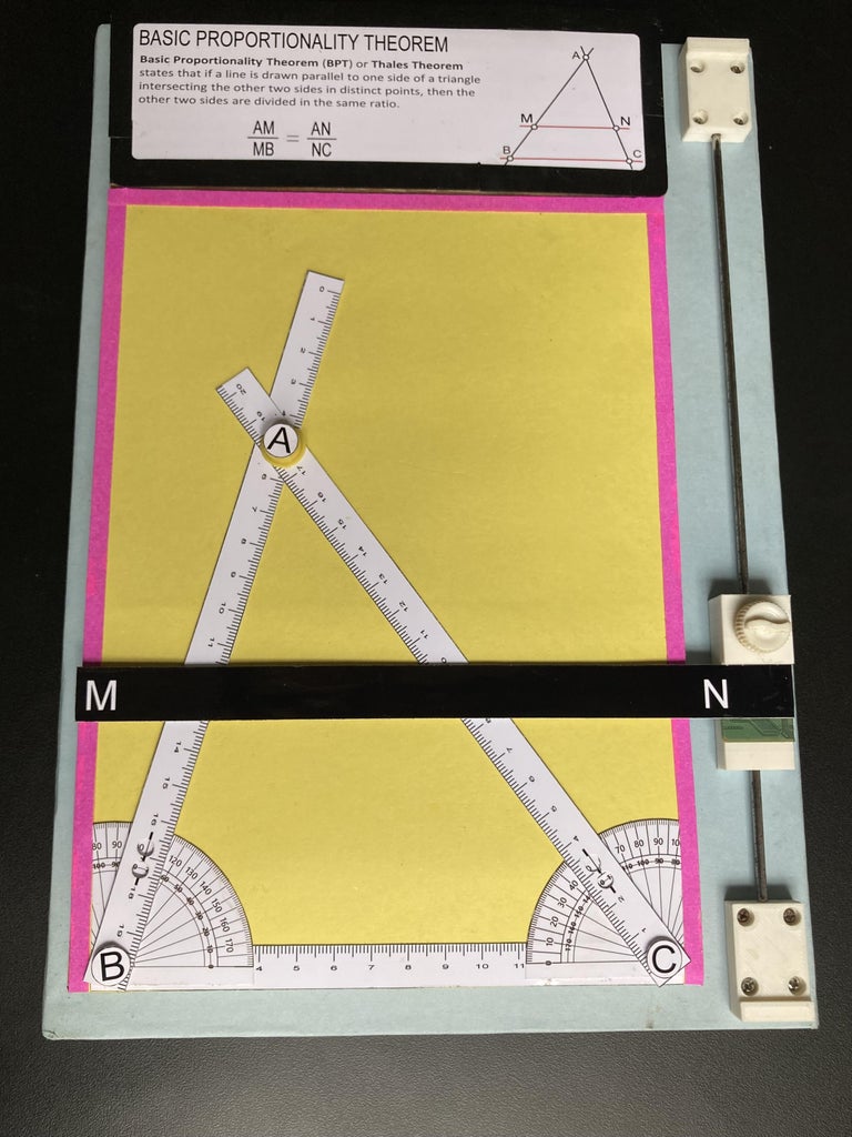
Thales Theorem or Basic Proportionality Theorem (BPT) states that if a line is drawn parallel to one side of a triangle intersecting the other two sides in distinct points, then the other two sides are divided in the same ratio.
This tangible model illustrates the Basic Proportionality Theorem with a parallel line intersecting a triangle.
To create a working model of basic proportionality theorem, we can use simple materials like cardboard, rulers, and scrap materials. Here's a step-by-step guide:
Supplies


Rectangular sized MDF board (2.5mm thick)
3d printed parts
Steel rod (length = 280 mm diameter = 2.8mm)
Screws / star head screws
Black ink Marker
A4 photo paper sheet
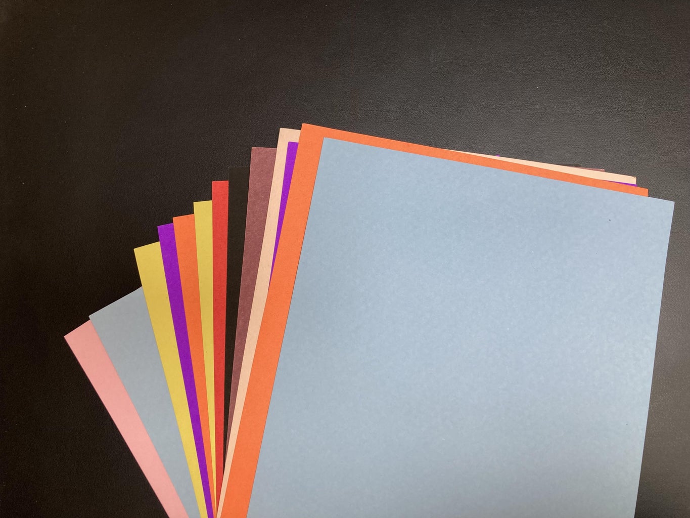
Colorful papers for decoration
Adhesive Glue
Super glue
PCB strip from old LED TV (for the parallel line)
Knob screw (1pcs)
Try square
Double sided foam tape
Circular Neodymium magnet (diameter = 10mm)
Iron plates from old transformer
Adhesive paper sheet
Plastic button (diameter = 10mm)
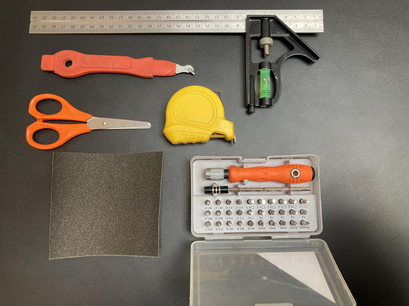
Tools:
MDF board cutter
Pen knife for cutting Cardboard sheet
Mini drill machine with drill bit (size= mm)
Color printer
3D printer
Measuring scale
Screw driver set
Scissors
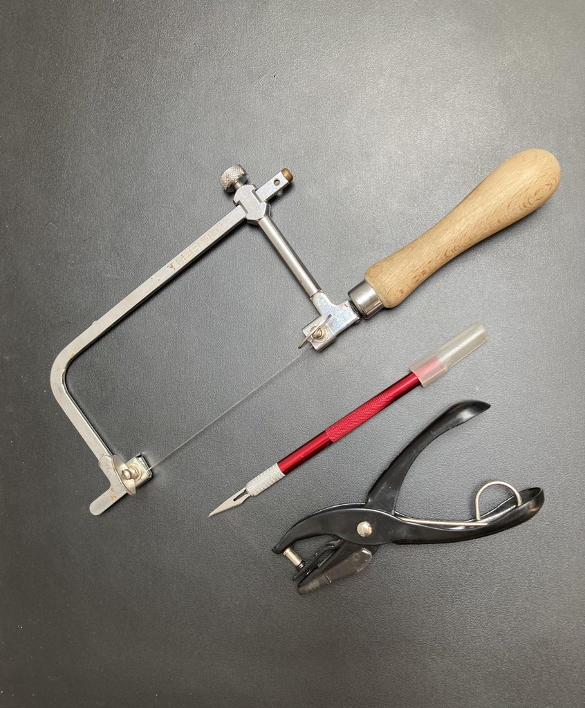
Hand saw
Single hole paper punch pliers
3M 150 Grit Sandpaper
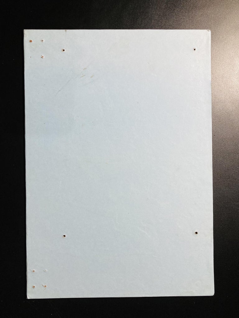
Step 1: Preparing MDF Board


We have to prepare two MDF Boards. One board act as the base and another for triangle set.
Cut two boards of dimension for base (30cm X 21cm) and for triangle set (23cm X 17cm)
Use a measuring tape and pencil to measure and mark the desired length on the MDF board. Ensure your marks are straight and even.
Align the MDF board cutter with your marked line and carefully cut the MDF board along the marked length.
Use sandpaper to smooth any rough edges created during the cutting process. This will provide a clean and finished look.
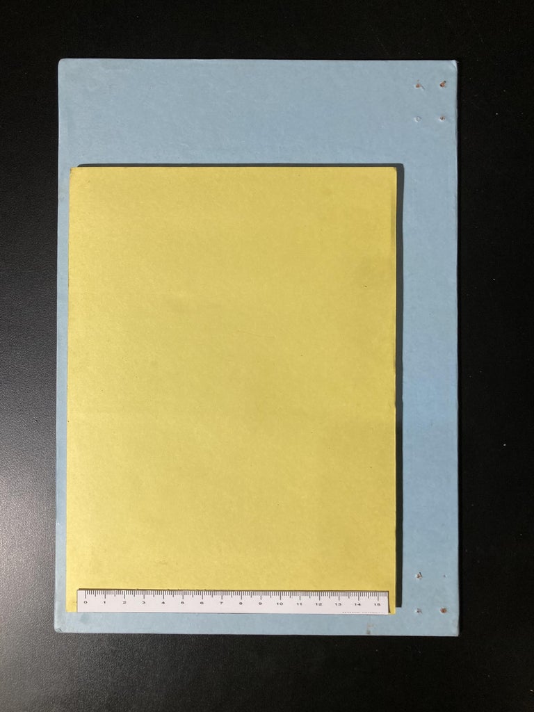
Cut the colorful papers into desired shapes or sizes for decoration. Consider a variety of colors and patterns for a vibrant look.
Apply glue to the surface of the MDF board. Work in small sections to prevent the adhesive from drying before you apply the paper.
Place the cut colorful papers onto the glued surface, arranging them as you desire. Smooth out any bubbles or wrinkles.
Let the decorated MDF board dry completely before handling or displaying.
Now we have two MDF board decorated with colorful papers. This can be a great base for this project.
Step 2: Design the Slider Mechanism


Creating a slider mechanism using a steel rod and a 3D-printed slider involves a few steps:
I Used Tinkercad to design the slider. Ensure it has an opening or groove to accommodate the steel rod.
Use 3D printer to create the slider based on your design. Ensure the dimensions match the steel rod's diameter.
Cut the steel rod of length 280mm using a saw. Make sure it's smooth and free of any sharp edges with the help of sand paper.
Slide the steel rod through the opening or groove in the 3D-printed slider.
Use 4 screws to each side hold the 3D printed slider ends to secure the 3D-printed slider onto the MDF Board. Make sure it allows smooth movement along the rod.
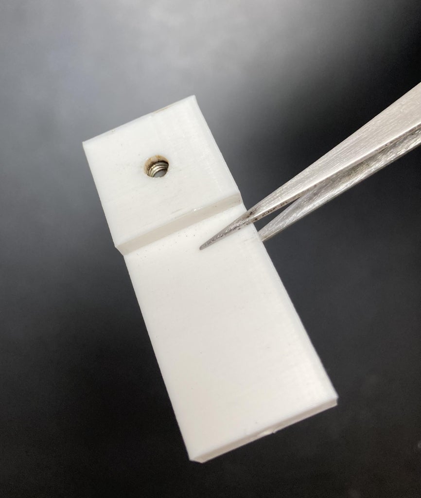
I used a knob screw on the slider to hold the slider on a particular position.
Insert the nut of the knob screw in the cavity provided in the slider block.
Slide the 3D-printed slider along the steel rod to test the mechanism. It should move smoothly without any excessive friction.
i used a PCB Strip got from a old LED TV to be used as a parallel line. Remove SMD components from the PCB strip with the help of sand paper.
Cut a desired length of PCB Strip with the help of Hand saw and paste its broader end on the top of the slider with the help of super glue. This PCB strip act as a parallel line and slider helps it to move it up and down.
On the PCB strip, paste a line segment M-N(representing parallel line) with the help of glue.
Step 3: Construction


Drill four holes according to the slider ends holes on the base board at upper right and lower right ends. Ensure that the holes are aligned properly.
On the back of triangle board paste old transformer iron plates with the help of glue and cover it with an adhesive paper sheet. You can use a magnetic sheet in place of iron plates.
This is done to place the variable vertex button A of triangle at different places to form different triangles.
Take a print out of pdf file file attached below on a 250 gsm photo paper. Cut out rulers/ scales, line segment M-N and two protractors.
On the scales two big blue dots and one small blue dot is shown. Make holes on the big blue dots with the help of punch pliers. Through these holes we can see angle reading on protector made by the scales. And make a pin hole the small dot using a sharp pin.
NOTE: Care should be taken while working with sharp objects.
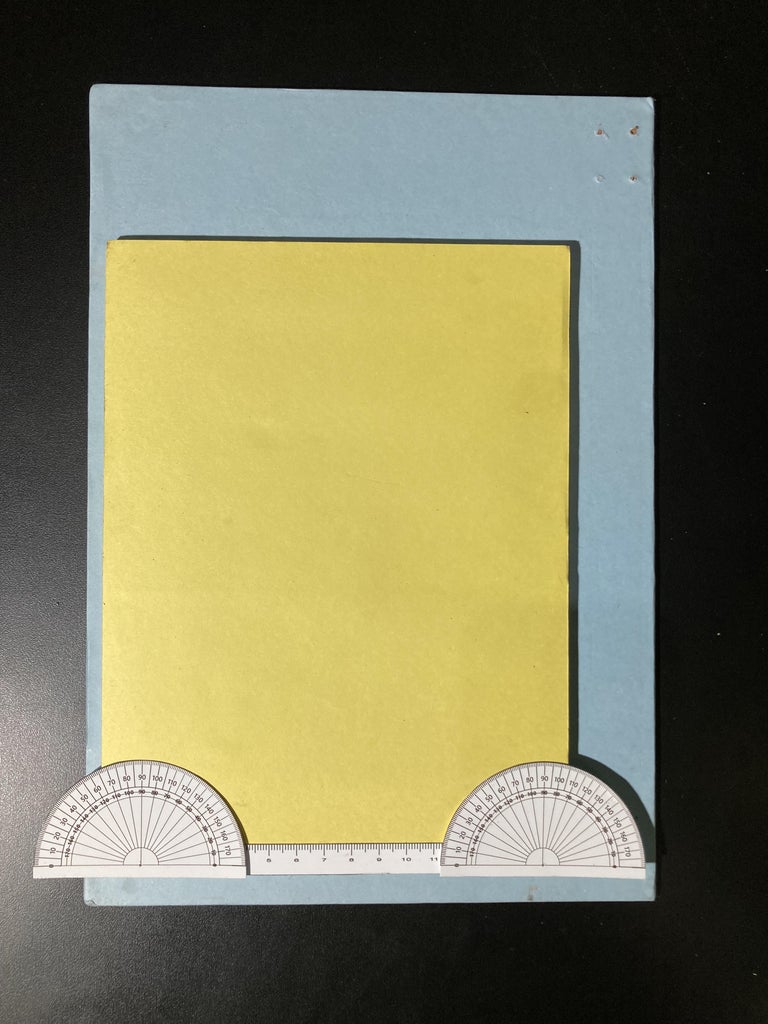
Attach the triangle set board on the base board with the help of double-sided tape at four corners as shown in the image.
Cut a paper scale of 15.5cm and paste it at the bottom of the triangle set board. This scale works as the base of the triangle.
Now cut two protractors in two halves as shown in the image and paste these protractors on the lower left and right corners of the triangle set board. These protractors help in determining the angles subtended by moving scales (sides of triangle).
Use two flat head screws to hold the scales on the protractors. Remember that the screws should not be tight. The screws act as pivot for the scales.
Label the vertices as A, B, and C.
Integrate the steel rod and slider mechanism onto the base board.
Paste colorful paper strips on the edges of board to make the model visually appealing.
All done.
Step 4: Working and Calculation

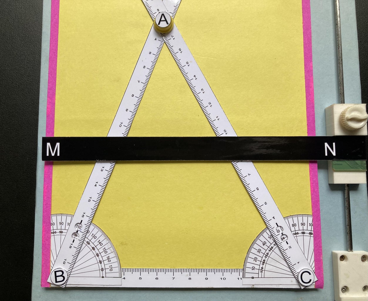
Make a random triangle with different sides by moving side scales and join the vertex of the triangle by placing Circular Neodymium magnet (Vertex A).
Now Slide the Parallel Line (M-N) with the help of slider over the triangle. Label the points where it intersects sides AB and AC as M and N, respectively.
Count readings on ruler to measure the lengths of segments AM, MB, AN, and NC.
Verify that the ratio of AM to MB is equal to the ratio of AN to NC.
Step 5: Example-1

Here the lengths of each line segment
AM = 6.6 cm
MB = 9.4 cm
AN = 7 cm
NC = 10 cm
Now the ratio of AM/MB= 6.6/9.4 = 0.70 and AN/NC = 7/10 = 0.70
Here we can see that the ratios AM/MB = AN/NC = 0.70 are equal.
Step 6: Example-2

Here the lengths of each line segment
AM = 5.5 cm
MB = 8.5 cm
AN = 6.6 cm
NC = 10.4 cm
Now the ratio of AM/MB= 5.5/8.5 = 0.64 and AN/NC = 6.6/10.4 = 0.64
Here we can see that the ratios AM/MB = AN/NC = 0.64 are equal.
From the above examples it is Verified that the ratio of AM to MB is equal to the ratio of AN to NC. This demonstrates the Basic Proportionality Theorem.
Step 7: 3D Model Files


Step 8: Conclusion
1. Basic Proportionality Theorem can be applied to any triangle regardless of its size and shape.
2. Thales Theorem can only be applied if the line joining the sides of a triangle is parallel as it is the necessary condition for the theorem.
3. Converse of the Basic Proportionality Theorem states that if a line intersects two sides of a triangle and divides the sides proportionally, then the line is parallel to the third side of the triangle.
Hope you like this project. Thank you

Participated in the
Anything Goes Contest


